To repurpose the CVS camcorder you need a custom cable. You can do this by soldering the end-connector from a Palm Pilot synch cable to USB cable. USB connectors have 4 conductors: +5v, ground, +data, -data. The USB cable's wires are nominally colored black, white, green and red.
 When you build a cable, you need to test it. Ohming out a cable entails attaching a multimeter to both ends of the cable. This can be a 3 or 4-handed job. To make this easier, I built a test jig as pictured here.
Someone gave me a dead motherboard with USB ports on it. I desoldered the USB sockets (with ethernet connector) pictured at the left. Then I soldered four clip leads to the USB signals coming out of the gizmo. Those four wires sticking out the top end in alligator clips. On the front of the block you'll see two USB sockets and an ethernet socket. The leads are connected to the top USB socket.
To ohm out your cable, plug the USB end in the socket and orient yourself with the Palm side of the cable. Orient the Palm connector with conductors facing upward, and the edge facing right. You'll see a row of 10 conductors. The first is on the left and the 10th is on the right.
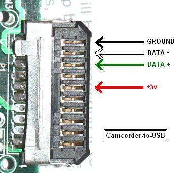 Clip the black lead to your multimeter. Touch the other side of your multimeter to the 10th pin on the Palm connector. It should be connected. Move on to the white lead. Attach it to the multimeter and check the 9th pin on the Palm connector. The green lead should match the 8th pin. Skip the 7th pin and check that the red lead matches the 6th pin on the Palm connector.
If all these signals work, you should be good to go. BUT first check to make sure no adjacent lines are shorted together. There should be no connection between pin 10 and 9, 9 and 8, 8 and 7, or 7 and 6. A bit of solder bridged pins 6 and 7 and that prevented the cable from working (despite ohming out correctly). Use a bright light and a magnifying glass to inspect your solder connections.
Further reading:
http://www.rkawakami.net/dakota/index2.html
http://www.mrbill.net/cvscam/cvscamera-cable-howto.pdf
http://www.maushammer.com/systems/dakotadigital/usb-cable.html
http://www.camerahacking.com/
Acknowledgement: I lifted the second image from "Maxwell Smart" on the camerahacking disussion forum. I definately recommend lurking there.
No comments:
Post a Comment